


Implementing Server–Client Synchronization for Multi-Panel LED Display Systems Using ESP8266
 View
View
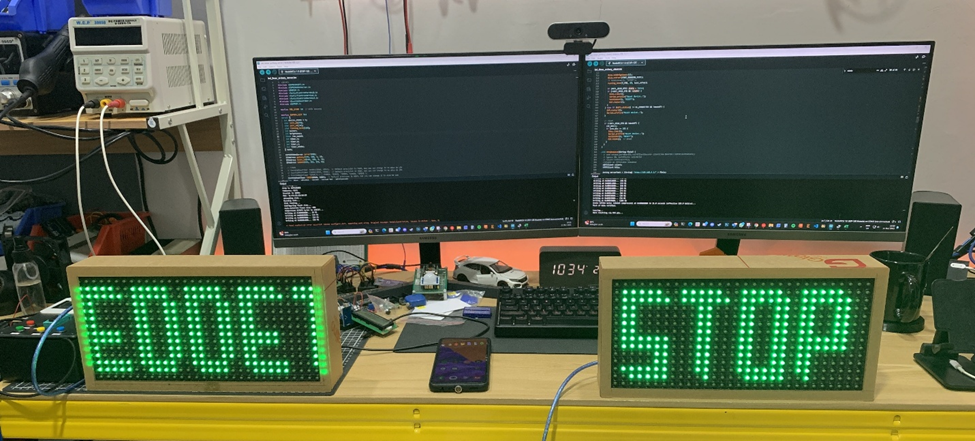
In large-scale timing applications such as sports competitions, a single LED display panel is often insufficient. To improve visibility across wider areas, multiple synchronized display units are required. In the WiFi-based LED countdown project, a server–client architecture was implemented using ESP8266 modules to ensure synchronized timing across multiple P10 LED panels.
This article explains how synchronization was achieved and the engineering considerations behind it.
System Architecture
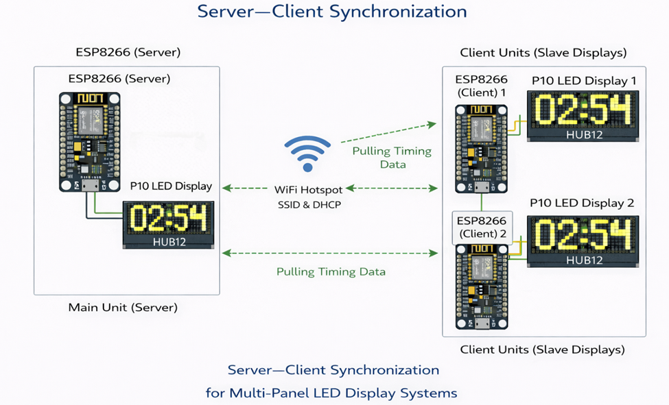
The system consists of:
- One Main Unit (Server)
- One or more Client Units (Slave Displays)
- WiFi network (Access Point mode)
The main device generates the countdown logic and broadcasts timing data. Client units do not compute countdown independently. Instead, they receive synchronized timing parameters from the server.
This prevents drift between displays.
Why Server–Client Instead of Independent Timers?
If each device runs its own internal countdown:
- Clock drift may occur
- Pause/Resume may desynchronize
- Network delay may cause mismatch
- Reset timing may differ
By centralizing logic in the server:
- Only one authoritative timer exists
- All displays follow the same reference
- State changes propagate simultaneously
This ensures deterministic synchronization.
Communication Strategy
The ESP8266 server operates in WiFi mode and handles:
- Timer start
- Pause
- Reset
- Brightness setting
- Running text updates
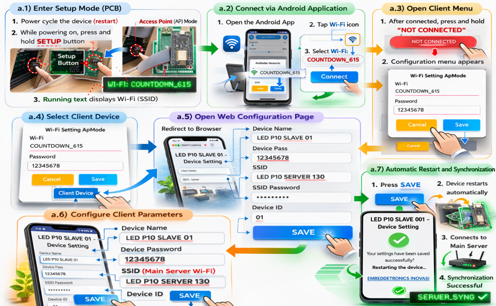
Client configuration step, where each slave device connects to the server using:
- SSID
- Password
- Device ID
Once connected, clients listen for timing packets.
Data Synchronization Logic
Instead of transmitting every second tick, the server sends:
- Initial countdown value
- State command (RUN / PAUSE / RESET)
- Periodic synchronization update
Clients use:
- Received time reference
- Local timer interrupt
- Periodic correction from server
If discrepancy is detected, the client adjusts its timer to match the server.
This reduces network traffic while maintaining accuracy.
Handling Network Instability
WiFi-based systems are susceptible to:
- Packet loss
- Temporary disconnection
- Signal interference
To mitigate this:
- Clients reconnect automatically
- Timeout detection triggers re-synchronization
- Countdown state is revalidated after reconnection
This ensures system reliability even in unstable environments.
Engineering Challenges
During implementation, several issues were encountered:
- Display update blocking network handling
- Timing jitter during heavy WiFi traffic
- Delayed synchronization when multiple clients connected
Solutions included:
- Non-blocking firmware structure
- Lightweight synchronization packets
- Separation between display refresh and WiFi tasks
Conclusion
The server–client synchronization architecture transforms a simple LED timer into a scalable multi-display system. By centralizing timing control and distributing synchronized updates, the system achieves reliable operation across multiple panels.
This approach can be extended to industrial dashboards, production counters, and large event displays.
#LEDProject##ESP8266##ServerClient##WiFiSynchronization##P10Display##LEDMatrix##HUB12##EmbeddedNetworking##MultiPanelDisplay##IndustrialDisplay#
 #LEDProject#
#ESP8266#
#ServerClient#
#WiFiSynchronization#
#P10Display#
#LEDMatrix#
#HUB12#
#EmbeddedNetworking#
#MultiPanelDisplay#
#IndustrialDisplay#
#LEDProject#
#ESP8266#
#ServerClient#
#WiFiSynchronization#
#P10Display#
#LEDMatrix#
#HUB12#
#EmbeddedNetworking#
#MultiPanelDisplay#
#IndustrialDisplay#
Sign In Or Register Comment after
No comments yet. Be the first to comment!